Siemens Hicom-118. SMDR/CDR data format and connection settings
Connection parametersThis information is applicable for: Hicom 100, Hicom 110, Hicom 120
Data for Call-Duration Recording Line-Related Data for CDR System Data for Printer and Interface Followed by blank lines: N CDR Data Record Set elements to one of the following configurations:
Pinouts PC to Hicom (via standard patch lead)DB25 1 – DB 9 1 – BLACK
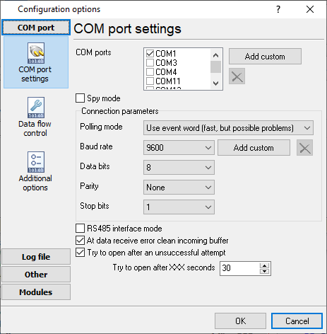
Configuring a COM portThe COM port number should match the number in your system. You can check the correct port number in Devices Manager → Ports. 1. Add a new configuration with the RS232 data source (if you didn't it before).
2. Select the COM port and configure the communication settings for your PBX corresponding to your PBX settings. 

Selecting the correct parser for Siemens Hicom-118
Siemens Hicom-118 Siemens Hicom-118 Data items
Interested in reports for PBX usage?We provide the PBX Reports utility, featuring a range of manual, scheduled, and email reports, a built-in web server, among other features. Implement your call accounting system for Siemens Hicom-118. Check our PBX Reports utility. Want PBX call logs in a database?This standard feature allows the logger to capture and export SMDR or CDR data in real-time directly to your database. Check our article about call logging to a database. Siemens Hicom-118 related connection settingsSiemens HiPATH 1100Shoretel 9 Siemens Hicom-150 OfficeCom v2 Siemens Hicom-150 OfficeCom Quick jump to the connection settings for other PBXs or connection formats ↴ Note: Products and companies mentioned here are used only for definition and identification purposes and can be trademarks and/or registered trademarks of the respective companies. |
|||||||||||||||||||||||||||||||||||||||||||||||||


