Most Popular RS232 or Computer Serial Port Connectors
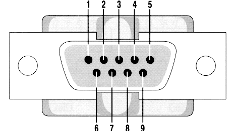
Fig.1 RS232/V.24 DB9
| Pin | Name | Description |
|---|---|---|
| 1 | CD | Carrier Detect |
| 2 | RXD | Receive Data |
| 3 | TXD | Transmit Data |
| 4 | DTR | Data Terminal Ready |
| 5 | GND | System Ground |
| 6 | DSR | Data Set Ready |
| 7 | RTS | Request to Send |
| 8 | CTS | Clear to Send |
| 9 | RI | Ring Indicator |
X.21 interface on a DB 15 connector

Fig. 2. X.12 DB15 connector
RJ-45 RS232 connector
EIA-561 defined RS232 on RJ 45 (modular) connector. It can be used only for non-synchronous applications because it does not have synchronous clocking signals. Note: The RI pin (#1) sometimes can be used as DSR.
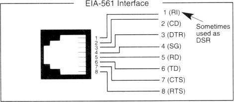
Fig.3. RJ-45 RS232 connector
RJ45 RS232D connectors (same as telephone connectors)

| Pin No. | Signal Description | Abbr. | DTE | DCE |
|---|---|---|---|---|
| 1 | DCE Ready, Ring Indicator | DSR/RI | ← | → |
| 2 | Received Line Signal Detector | DCD | ← | → |
| 3 | DTE Ready | DTR | → | ← |
| 4 | Signal Ground | SG | ||
| 5 | Received Data | RxD | ← | → |
| 6 | Transmitted Data | TxD | → | ← |
| 7 | Clear To Send | CTS | ← | → |
| 8 | Request To Send | RTS | → | ← |
DB25 V.24 pinout and signals
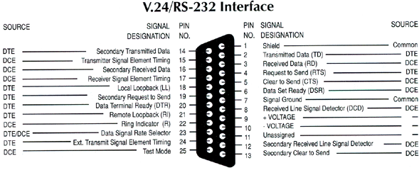
Fig.4. RS232 V.24 connector
DB25 V.24 pinout and signals (ALT A connector)
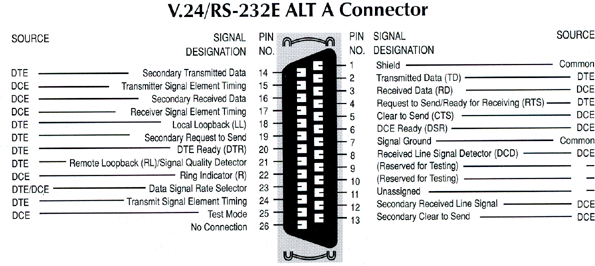
Fig.5. RS232 V.24 (ALT A) connector
RS232 DB25 all pins (some applications require more pins)
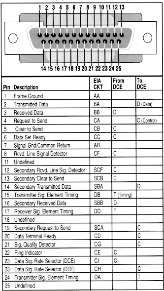
Fig.6. RS232 DB25 connector
Our software allows you monitor, log, debug and test your RS232 or COM ports.